Two Wire Pressure Transmitter Wiring Diagram
![]()
Two wire pressure transmitter wiring diagram. 2, 3 and 4 wire loops in their vary basics. Unscrew the cover of the transmitter housing. A lot of loop setups will utilize an external power supply in order to power the devices which are attached to the current loop. This manual should be used in conjunction with the tronic line data sheets.
Establish the necessary pressure connection to the transmitter in the external 1/2” nptm or internal 1/4” nptf appropriately. Connect the + (red) lead of the transmitter to Next is a resonance stage and the final stage built with a minimum 1w transistor which must have a heatsink. Depending on the sensor type used, the processed signal is provided as an analog output signal 4.
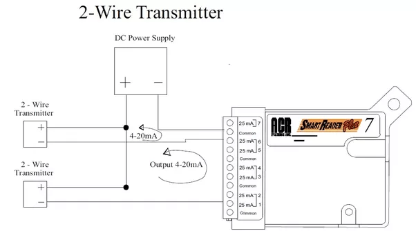
It reveals the parts of the circuit as streamlined shapes and the power as well as signal connections in between the gadgets. 2 wire pressure transmitter wiring diagram. A 2 wire transmitter has only 2 wires and is connected in series with the power supply and the plc. Using a multimeter as the acquisition device, the sampling resistance is 250 ohms, the zero current is 4 ma, and the collected voltage is about 0.997 v (0.004 ma × 250 ohm = 1 v).
However, a separate power supply is also available as an option. Mount the transmitter so that the drain/vent valves are oriented upward. The schematic diagram below shows the wire transmitter configuration: 2 wire transmitter current loop.
2 wire pressure transmitter wiring diagram. This diagram illustrates the correct wiring. Place taps in the top or side of the line. 2, 3 and 4 wire loops.
This is one of the simplest wiring types as it only has two wires. 2 wire transmitter wiring diagram. Either the transmitter or the receiver would provide the power supply to the loop. It is assumed that the measurement device includes a sufficient load resistance for measuring a current loop.
The ceramic diaphragm is unbalanced in proportion to the pressure applied. The power supply and the instruments are usually mounted in the control room. The actual wiring between the transmitter and the power supply depends upon whether it is a 2 wire or a 4 wire type. Two wire pressure transmitter wiring diagram.
Pressure transducers that output milliamp signals can connect to multiple devices in series. A 4 wire transmitter has 2 wires connected to a power supply and 2 signal wires connected to the plc. Place taps to the side of the line. It is a simulation diagram of the actual application in figure 2.
It shows the parts of the circuit as streamlined forms and also the power and signal connections in between the gadgets. Mount beside or below the taps. Be sure the pressure passage inside the port is not blocked. Mount beside or above the taps.

3 Wire Transducer Wiring Diagram / 3 Wire Proximity Sensor

Need more current than 4 mA in 4/20mA loop current

4 to 20 mA Current Loop Output Signal

Pressure Transducer Wiring Diagram PURPLEITUUNGGU

4 20ma Pressure Transducer Wiring Diagram Free Wiring

APB3V High Accuracy, Low Cost 420mA Vacuum Pressure

4 20ma Pressure Transducer Wiring Diagram Free Wiring

Pressure Transducer Wiring Diagram Free Wiring Diagram

MIKP300 Pressure TransmitterHANGZHOU MEACON AUTOMATION

420 mA Transmitter Wiring Types 2Wire, 3Wire, 4Wire

Pressure Sensor for Air/Water/Oil, 420mA/05V/RS485

Pressure Transducer Wiring Diagram
What is the difference between two wire and four wire

Voltage Output Pressure Transducer Comparison TE

2Wire 420 mA Sensor Transmitters Understanding the 2

Pressure Transmitters Wire Configuration Learning

Pressure Sensor vs Transducer vs Transmitter TE Connectivity

Wiring Diagram For Pressure Transducer

2 Wire Dc Proximity Sensor Wiring Diagram Download

Pressure Transmitter Circuit InstrumentationTools

Pressure Transducer Wiring Diagram General Wiring Diagram

4 Wire Pressure Transducer Wiring Diagram Drivenheisenberg

4 20ma Pressure Transducer Wiring Diagram Sample

How to Calibrate a Rosemount 1151 Pressure Transmitter

4 Wire Pressure Transducer Wiring Diagram Drivenheisenberg