Ideal Logic Combi 30 Wiring Diagram
Ideal logic combi 30 wiring diagram. External programmers for combination boilers. Platto program, refer to the user guide supplied with the kit 2 1 4 3 mechanical timer blanking e fitting instructions. I've set up tado with an ideal logic combi 35 using opentherm. What i am struggling with is the 'call for heat' wire.
Ideal logic heat h 15 wiring diagram heating spare parts. It has an internal clock, 2 port zone valves and 2 programmable room stats which are esi esrtp4. Wiring a honeywell thermostat to a worcester boiler moneysavingexpert forum. I have wired in the nest and connected up the permanent live and neutral.
New build completed in october just before they moved in. On your pic the existing wires are the ones for the existing stat which get removed, correct ? Remove the link wire plug and discard. Wire a nest thermostat up to a logic+ combi boiler!
Rvht 2 wireless timer thermostat control ravenheat. I have an ideal logic 30 combi boiler, and had a honeywell r6660d receiver and simple wireless thermostat. These are the simplest systems, as the only controls are those for central heating. Nest heat link control wiring to ideal logic plus 30 boiler overclockers uk forums.
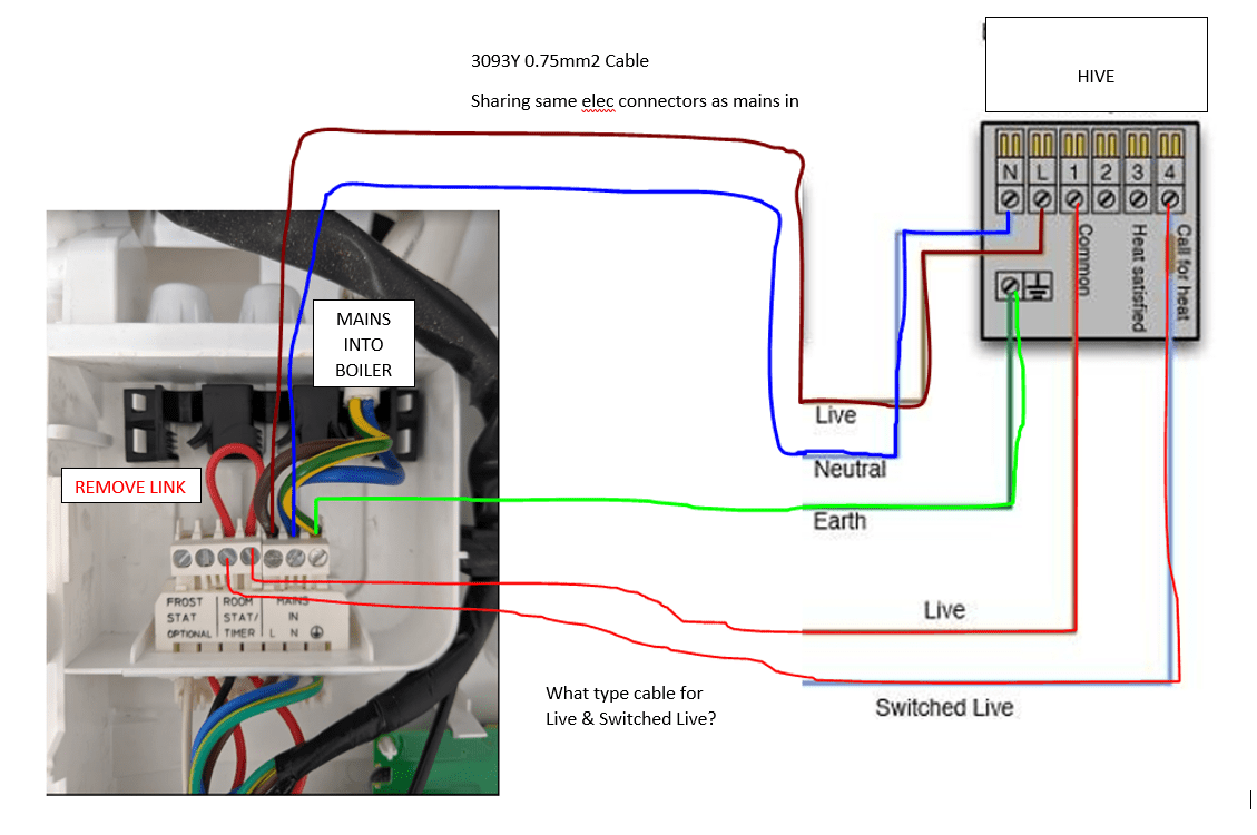
Boiler diagrams, spare parts and user manuals for ideal logic + combi c30 (controls) | 24 hour delivery on genuine manufacturer boiler spares | 30 day money back guarantee Hive 2 wiring help with ideal independent 30 combi boiler diynot forums. A two wire plug connects to the pcb for the weather compensation part and then the opentherm plug connects to the harness. Ideal relay transceiver wiring (y plan diagram) ideal relay transceiver wiring (s plan diagram) *where the ideal touch kit is being fitted to an existing installation (s or y plan), the wire connecting any sl in on the boiler requires disconnecting and making safe.
Product literature & user guides. Logic esp1 combination boiler ideal boilers erp data symbol units model 24 30 35 condensing boiler yes seasonal space heating efficiency class a rated heat output kw 24 seasonal space heating energy efficiency ƞ s % 94* annual energy consumption q he gj 75 sound power level, indoors l wa db 48 46 44 water heating energy efficiency class a It is possible that the original thermostat was originally incorrectly installed and the brown and black wires are. A combination boiler, or combi, is a boiler which heats hot water on demand, and additionally can function as a normal boiler to heat hot water for radiators.
Connect the electrical plug as shown. Supplied by www.heating spares.co tel. As you can see it only has 5 wires, earth, live, neutral, t1 & t2. Our handy user manuals for ideal boilers, thermostat controls and accessories are yours to download and keep.
My name is clint and i was wondering if somebody out there could do me a wiring diagram for the following boiler which is an ideal, logic combi esp1. Hi, is the boiler your using an ideal logic combi esp1 35 ? Boiler diagrams, spare parts and user manuals for ideal logic combi 30 (boiler exploded view) | 24 hour delivery on genuine manufacturer boiler spares | 30 day money back guarantee Using the live neutral and earth i will connect the cable from the boiler power marked with a plug on the boiler diagram in this post to the n l and earth tether on hive.
I have an ideal logic 30 combi boiler and had a honeywell r6660d receiver and simple wireless thermostat. My son lives in an apartment which appears to have 2 stats, 1 in the master bedroom the other in the hallway. Installation help ideal code combi esp1 38 tado community. Boiler diagrams, spare parts and user manuals for ideal independent combi 30 (wiring diagram) | 24 hour delivery on genuine manufacturer boiler spares | 30 day money back guarantee
And the hive single channel receiver needs 6,. Ideal logic combi 24 wiring diagram heating spare parts heat h 18 system s30 central diagrams 35 esp1 c30 pump overrun diynot forums icos he15 combination boiler with 2 zones 230v switching y plan volt free exploded view nest 3rd gen 30 hive for a 12 installation and servicing pdf manualslib how works design boffin does an s work boilers i. Based on the diagram below from the logic 30 boiler manual the live brown wire should go to l the neutral grey wire should go to n the black wire should go the the very end terminal of the terminal strip marked room stat / timer. Ive noticed the new ideal logic boilers electrical terminals have now changed there used to be a pump over run terminal in the boiler labeled pump, now the new terminals are just permanent supply and sl1 which shows on the wiring diagram is connected to the port valve orange , this is obvious a switch live to fire the boiler but how is the the pump over run going to.
Combination boiler with 2 heating zones 230v switching. Attached is the wiring diagram for the receiver. Ideal logic heat 12 installation and servicing pdf manualslib. Discussion in 'electricians' talk' started by tim jolley, jan 11, 2018.
Boiler diagrams, spare parts and user manuals for ideal logic combi 30 (wiring diagram) | 24 hour delivery on genuine manufacturer boiler spares | 30 day money back guarantee

Ideal Logic Wiring Diagram Wiring Diagram

Boiler Manuals Ideal Logic + Combi 30 Products

Wiring Diagram For Ideal Logic Combi Wiring Diagram and
Wiring Diagram For Ideal Logic Combi Wiring Diagram and

Ideal Logic combi 30 Boiler Compass Plumbing & Heating

Ideal Logic Combi 24 Wiring Diagram Wiring View and

Hive 2 and Ideal Logic Combi 30 DIYnot Forums
![[DIAGRAM] Ideal Logic Combi 30 Diagram FULL Version HD](https://i2.wp.com/webimg.secondhandapp.com/w-i-mgl/5ae86a93a066881452c94046)
[DIAGRAM] Ideal Logic Combi 30 Diagram FULL Version HD

Hive with Logic Combi 30 Wiring Problems DIYnot Forums

Ideal Logic Wiring Diagram Wiring Diagram

Ideal Logic Combi 24 (Boiler Exploded View ABK Onwards

Ideal Logic Combi 24 Wiring Diagram Wiring View and

Ideal Logic Combi 24 Wiring Diagram Wiring View and
![[DIAGRAM] Ideal Logic Combi 30 Diagram FULL Version HD](https://i2.wp.com/www.diynot.com/diy/media/2017-11-30-19-41-41.100778/full)
[DIAGRAM] Ideal Logic Combi 30 Diagram FULL Version HD

Ideal Logic Combi 30 Spare Parts List Reviewmotors.co

Ideal Logic Wiring Diagram Wiring Diagram

Ideal Logic Combi 30 Pressure Gauge. Where is it ? YouTube

Ideal Logic Combi 24 (Gas Management ABK Onwards)Diagram

Wiring Diagram For Ideal Logic Combi Wiring Diagram and

Ideal Logic Combi ESP1 35 Installation manual Page 49

Ideal Logic Wiring Diagram Wiring Diagram

Ideal Logic Heat 18 Wiring Diagram Wiring Diagram

Hive with Logic Combi 30 Wiring Problems DIYnot Forums

Installing Hive to Ideal Logic Combi Boiler DIYnot Forums

Ideal Logic Combi 24 Wiring Diagram Wiring View and